That complexity matters for inspection outcomes. According to NREL's 2024 SolarAPP+ Performance Review, roughly 35% of traditional residential PV projects fail their first inspection, with 79% of reported failures tied to code compliance issues. Ground mount systems add site-specific layers — soil conditions, burial depth verification, structural plan checks — that increase that risk considerably.
This guide covers the complete wiring and raceway protection process for ground mount solar: conduit selection, burial requirements, step-by-step wiring sequence, grounding, and the most common inspection failures and how to fix them. Wiring and raceway work should be performed by a licensed C-46 Solar Contractor or C-10 Electrical Contractor — errors in conduit sizing, burial depth, or grounding continuity create fire risk, shock hazards, and failed inspections.
Key Takeaways
- Wiring must enter a raceway (typically EMT conduit) before leaving the array — required under NEC Article 690.31
- Three protection methods exist: underground conduit, direct burial cable, and cable hangers — each suited to different site conditions
- All metal components must be bonded and grounded via an EGC and GEC connected to a physical grounding electrode
- Burial depth, conduit type, and conductor sizing come from the engineering diagram — never improvised in the field
- California AHJs interpret NEC differently by jurisdiction; confirm local requirements before interconnection approval
Raceway Protection Options for Ground Mount Solar
For homeowners planning a ground mount system, understanding how wiring gets protected from the array to your home is one of the most consequential installation decisions you'll make. NEC Article 690.31 requires solar wiring to transition into a raceway protection system before leaving the array. Three primary methods exist, and the right choice depends on site conditions, soil characteristics, and what your local AHJ will approve.
Underground Conduit: EMT and PVC
EMT (Electrical Metallic Tubing) is the standard above-grade raceway under most California building codes. It must be grounded, provides rigid mechanical protection, and is suitable for exposed or concealed installations in dry, damp, or wet locations with appropriate fittings per NEC Article 358. The local AHJ must explicitly approve ENT (non-metallic flexible conduit) — treat it as a limited-use option, not a default.
For underground runs, PVC Schedule 40 or Schedule 80 is the common choice:
- Schedule 40: Suitable for underground and outdoor exposed locations where physical damage is not a concern; must be listed for sunlight resistance if used above grade
- Schedule 80: Required where physical damage exposure is expected (above-grade sections near vehicle traffic, equipment, or impact zones)
- Conduit protects wire from crushing, moisture, rodent damage, and abrasion — and allows wire replacement without re-digging
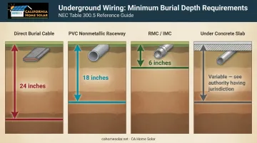
NEC Table 300.5 specifies minimum burial depths:
| Wiring Method | Minimum Cover (General) |
|---|---|
| Direct burial cable | 24 inches |
| PVC (nonmetallic raceway) | 18 inches |
| RMC/IMC | 6 inches |
| Under 4-inch concrete slab | Lower values apply; verify with AHJ |
Direct Burial Cable
Direct burial-rated PV wire (certified under UL 4703) can be installed in trenches without conduit under specific conditions. UL notes that direct burial suitability is an evaluated use: only products explicitly marked "FOR DIRECT BURIAL" or "DIR BUR" qualify.
The practical risk in Southern California: rocky or angular native soil creates real damage exposure. SCE's underground conduit standard requires 3 inches of imported noncohesive sand bedding where native soils are hard or rocky, and CPUC General Order 128 prohibits backfill containing large rocks or sharply angular materials near buried cables.
In Southern California, the practical drawbacks are significant:
- Damaged wire requires full excavation to repair
- No protection against rodent damage or soil shift
- Many California AHJs prefer or require conduit regardless of NEC allowances
- No path for future wire replacement without re-digging
Cable Hangers (Above-Ground)
Galvanized steel cable hangers with PVC coating mount directly to racking and route PV wire above ground from panels to the combiner box. Per NEC 690.31(C)(1), cables 8 AWG and smaller require support every 24 inches; larger cables every 54 inches.
Cable hangers work well on rocky or sloped terrain where trenching is impractical. That said, the exposure limitations are real:
- Wire is exposed to UV, wind, vandalism, and accidental contact
- Acceptable in fenced, secured commercial arrays
- Not typically used on residential ground mounts in suburban Southern California, where exposed wiring creates both aesthetic and safety concerns
Step-by-Step: Wiring a Ground Mount Solar System
Ground mount wiring follows a defined sequence. Rushing or skipping any step creates inspection failures or long-term faults.
Prerequisites and Site Readiness
Before any trenching or wiring begins, confirm all of the following:
- Engineering/wiring diagram is finalized and specifies conduit size, wire gauge, burial depth, and run distance
- Call-811 underground line locates are completed
- Permits are pulled from the local AHJ
- Mounting structure is fully set with concrete piers cured (minimum one week; three weeks for full structural cure)
- Inverter mounting location is confirmed — this determines the entire conduit route
Non-negotiables:
- Do not start wiring on an unstable foundation
- Do not downsize conduit from what the wiring diagram specifies (upsizing is permitted, downsizing is not)
- For California projects, confirm which NEC edition your local AHJ has adopted under the 2025 California Building Standards Code (effective January 1, 2026) before finalizing the design — local interpretations vary across Southern California jurisdictions in ways that aren't always obvious from the code text
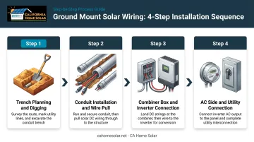
The Four-Step Wiring Sequence
Step 1 — Plan and dig the trench
Reference the wiring diagram for required depth and route. Call 811 before any digging. For most residential California ground mounts: PVC conduit requires 18 inches minimum burial; RMC requires 6 inches. Slope the trench bottom slightly to encourage drainage away from the array.
Step 2 — Install conduit and pull wire
- Lay conduit with sweep elbows at all grade transitions (never sharp 90-degree bends)
- Secure factory wire leads under the array at NEC-required intervals using cable clips
- Pull conductors through conduit per the wiring diagram — confirm wire type, gauge, and color coding before pulling; substitutions require engineering approval
- Calculate conduit fill before purchasing materials: NEC Chapter 9 Table 1 limits fill to 40% for three or more conductors
Step 3 — Connect the combiner box and inverter
- Wire PV strings from the array to the combiner/junction box
- Verify string polarity before making connections
- Mount the inverter above 36 inches on the substructure to prevent mud and moisture exposure; keep it shaded from direct sun
- Follow the wiring diagram for the DC combiner-to-inverter transition
Step 4 — Complete the AC side and utility connection
- Connect inverter AC output to the sub-panel or main panel via the AC disconnect
- In most California jurisdictions, the AC disconnect must be within line-of-sight of the meter
- Confirm breaker sizing matches the system design
- Do not activate the solar backfeed breaker until after inspection and interconnection approval from the utility
Grounding Your Ground Mount Solar System
Ungrounded or improperly bonded systems create shock hazards, fire risk from lightning strikes and ground faults, and will fail inspection. Ground faults and arc faults rank among the most common causes of PV array fires — a serious concern in LA County and Antelope Valley, where high-wind events stress connections and wildfire risk raises the stakes on any fault condition.
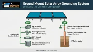
The Two Grounding Conductors
EGC (Equipment Grounding Conductor): The green or bare copper wire that bonds all metal components — panel frames, racking, EMT conduit, and enclosures — together into a single equipotential system.
GEC (Grounding Electrode Conductor): Connects the electrical system's ground reference to a physical grounding electrode, typically a copper-clad rod driven at least 8 feet into the ground per NEC 250.53.
Per NEC 250.64(B), GECs 6 AWG or larger that are exposed to physical damage must be protected using RMC, IMC, Schedule 80 PVC, EMT, or cable armor.
Bonding Requirements
All metal parts of the solar array must be bonded together to eliminate voltage differences between components:
- UL-listed racking systems with integrated bonding may use a single grounding lug per row
- Racking systems without integrated bonding require individual grounding lugs at every panel frame and every racking splice
- Use #6 AWG bare copper wire for grounding conductors under the array where physical damage exposure is possible
- LA County adds a local requirement: metallic fences guarding the array need specific bonding provisions beyond standard NEC minimums
Inverter Grounding: Confirm Before You Wire
Modern string inverters and microinverters manage DC system grounding internally. Adding an external ground bond where one already exists creates a ground fault condition — so confirm your inverter's grounding method before completing the circuit.
This applies to all common inverter brands used in Southern California installs:
- Fronius and SMA Sunny Boy string inverters
- SolarEdge with power optimizers
- Enphase IQ8 microinverter systems
Each handles grounding differently per its listing and manufacturer instructions. California building department inspectors will check this — document the grounding configuration clearly and keep it visible at inspection.
Common Wiring Problems and How to Fix Them
Issue 1: Conduit Sized Too Small for Wire Count
What goes wrong: Wires become impossible to pull cleanly, and insulation gets damaged in the process.
Fix:
- Calculate conduit fill percentage before buying materials using NEC Chapter 9 Table 1 (40% maximum for 3+ conductors)
- Upsize conduit when in doubt — the NEC permits it and it future-proofs the run
- If conduit is already buried, a parallel conduit run is often more practical than full replacement
Issue 2: Incomplete or Broken Grounding Continuity
What goes wrong: Inspections fail when a grounding lug is missing at a racking splice, EMT joints aren't bonded, or a grounding wire has a loose connection.
Fix:
- Test for electrical continuity across all metal components before inspection using a multimeter
- Add grounding bushings at every conduit termination
- Install individual bonding jumpers at all racking splices that are not UL-listed as self-bonding
Issue 3: Incorrect Burial Depth or Exposed Conduit Transitions
What goes wrong: Conduit buried too shallow, sharp 90-degree bends at grade transitions, or above-grade PVC that isn't rated for UV and weather exposure.
Fix:
- Confirm minimum burial depths against the wiring diagram and local AHJ requirements before backfilling
- Use sweep elbows at all grade transitions
- Use sunlight-resistant PVC above grade; choose Schedule 80 where physical damage is likely
- Use appropriate conduit bodies and fittings at all transition points
When in doubt on any of these issues, a licensed solar contractor can verify compliance before your inspection date — avoiding costly corrections after the fact.
Pro Tips for Wiring a Ground Mount System Correctly
Map the Full Route Before Digging
Identify every transition point, conduit body location, and pull box placement on paper before breaking ground. Confirm the route avoids future landscaping, irrigation lines, or hardscape plans — changes after conduit is buried are expensive and often require re-permitting.
Photograph Everything Before Backfilling
Document conduit runs, burial depths, grounding rod locations, and combiner box connections with photos before covering anything. California permitting offices increasingly request this documentation — and it pays off during maintenance calls, re-inspections, or warranty disputes years later.
Know Your AHJ Before Finalizing the Design
Jurisdiction requirements vary significantly across Southern California and can affect your conduit routing, structural calculations, and inspection timeline. A few examples:
- LA County triggers a site review and electrical plan check for arrays exceeding 72 inches above grade or on slopes steeper than 3:1
- Riverside County requires stamped structural calculations for ground-mount structures and enforces DC conduit labeling at 10-foot intervals
- Orange County cities often have additional setback and grounding requirements beyond standard NEC minimums
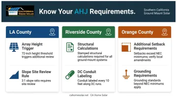
These details don't surface in a general code reading — they require familiarity with local AHJ practices to catch before design is finalized.
Pulling the permit application checklist from your specific AHJ — before finalizing the design — is the most reliable way to avoid a failed inspection or costly mid-project redesign.
Frequently Asked Questions
Does solar wiring need to be in conduit?
NEC Article 690.31 requires solar wiring to transition into a raceway before leaving the array. Direct burial-rated cable (UL 4703) is permitted underground under specific site conditions, but most California AHJs default to conduit for maximum protection.
Do ground mounted solar panels need to be grounded?
Yes. NEC Section 250 and NEC Article 690 both require it. All metal components — panel frames, racking, conduit — must be bonded together via an EGC, and the system must connect to a physical grounding electrode via a GEC.
What type of conduit is best for ground mount solar?
EMT is the standard above-grade choice for exposed runs. PVC Schedule 40 or 80 is commonly used for underground runs due to corrosion resistance. The wiring diagram and local AHJ requirements determine the approved conduit type for each project.
How deep does conduit need to be buried for a solar ground mount?
Burial depth depends on conduit type: PVC typically requires 18 inches minimum, RMC as little as 6 inches, and direct burial cable 24 inches under NEC Table 300.5 for general locations. Always confirm with the project's engineering report and local AHJ before digging.
What wire gauge is required for solar panel wiring?
The required gauge is specified in the system's wiring diagram, based on string current, run length, and voltage drop calculations. For grounding conductors exposed to physical damage under the array, #6 AWG bare copper is the standard reference point under NEC guidance.
Can I use direct burial cable instead of conduit?
Direct burial-rated PV cable is permitted where soil is soft, well-draining, and free from sharp rocks — but site conditions must be evaluated before choosing this route. Many California AHJs require conduit regardless, and conduit makes future wire replacement far easier without full excavation.